 Temperatura este parametrul cel mai frecvent măsurat, dar în multe privințe, este cel mai puțin înțeles. Temperatura este un parametru surprinzător de dificil de măsurat cu precizie, față de cât s-ar putea aștepta, în mod rezonabil. Pentru a obține o precizie mai bună de 0,2°C, este nevoie de multă atenție la sursele de erori. Erorile apar din cauza repartiției de gradienți de temperatură, de distribuția spațială a componentelor în proiect, neliniaritatea senzorului, de contact termic slab între senzor și dispozitivul măsurat, de abaterea de la calibrarea inițială, de energie radiantă și de autoîncălzirea senzorului.
În general, corectitudinea măsurării pentru orice tip de senzor poate fi mult îmbunătățită prin calibrare individuală. De aceea, pentru mai multe informații, consultați pagina tehnică corespunzătoare pentru fiecare tip de senzor.
Este măsurarea temperaturii dificilă?
Răspunsul depinde de gama de temperatură, materialul măsurat și cerințele de precizie. Tabelul de mai jos rezumă dificultatea de măsurare a temperaturii într-un interval de temperaturi:

Într-un laborator cu standarde și echipamente adecvate, este posibil să se măsoare temperatura cu precizia de 0,001°C (1°mC). Acest lucru se face de obicei prin interpolare (estimarea valorilor) între două standarde, folosind un senzor de temperatură de calitate, din Platină (Pt) și/sau un termocuplu de tip S.
La măsurarea temperaturii, este important să păstrați obiectivele, pentru a identifica exact ceea ce trebuie să fie măsurat și acuratețea necesară. În cazul în care diferențele exacte de temperatură sunt de primă importanță, se folosesc termocupluri pentru a evita nevoia de senzori selectați ca să fie pereche. Vezi: www.capgo.com, la capitolul Resources.

La măsurarea temperaturii, este important să păstrați obiectivele, pentru a identifica exact ceea ce trebuie să fie măsurat și acuratețea necesară. În cazul în care diferențele exacte de temperatură sunt de primă importanță, se folosesc termocupluri pentru a evita nevoia de senzori selectați ca să fie pereche. Vezi: www.capgo.com, la capitolul Resources.
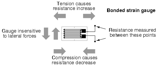
If a strip of conductive metal is stretched, it will become skinnier and longer, both changes resulting in an increase of electrical resistance end-to-end. Conversely, if a strip of conductive metal is placed under compressive force (without buckling), it will broaden and shorten. If these stresses are kept within the elastic limit of the metal strip (so that the strip does not permanently deform), the strip can be used as a measuring element for physical force, the amount of applied force inferred from measuring its resistance.
Such a device is called a strain gauge. Strain gauges are frequently used in mechanical engineering research and development to measure the stresses generated by machinery. Aircraft component testing is one area of application, tiny strain-gauge strips glued to structural members, linkages, and any other critical component of an airframe to measure stress. Most strain gauges are smaller than a postage stamp, and they look something like this:
A strain gauge's conductors are very thin: if made of round wire, about 1/1000 inch in diameter. Alternatively, strain gauge conductors may be thin strips of metallic film deposited on a nonconducting substrate material called the carrier. The latter form of strain gauge is represented in the previous illustration. The name "bonded gauge" is given to strain gauges that are glued to a larger structure under stress (called the test specimen). The task of bonding strain gauges to test specimens may appear to be very simple, but it is not. "Gauging" is a craft in its own right, absolutely essential for obtaining accurate, stable strain measurements. It is also possible to use an unmounted gauge wire stretched between two mechanical points to measure tension, but this technique has its limitations.
Typical strain gauge resistances range from 30 Ω to 3 kΩ (unstressed). This resistance may change only a fraction of a percent for the full force range of the gauge, given the limitations imposed by the elastic limits of the gauge material and of the test specimen. Forces great enough to induce greater resistance changes would permanently deform the test specimen and/or the gauge conductors themselves, thus ruining the gauge as a measurement device. Thus, in order to use the strain gauge as a practical instrument, we must measure extremely small changes in resistance with high accuracy.
Such demanding precision calls for a bridge measurement circuit. Unlike the Wheatstone bridge shown in the last chapter using a null-balance detector and a human operator to maintain a state of balance, a strain gauge bridge circuit indicates measured strain by the degree of imbalance, and uses a precision voltmeter in the center of the bridge to provide an accurate measurement of that imbalance:
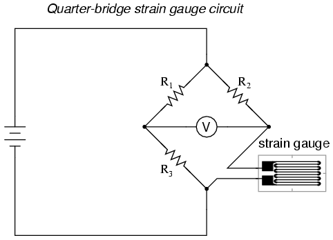
Typically, the rheostat arm of the bridge (R2 in the diagram) is set at a value equal to the strain gauge resistance with no force applied. The two ratio arms of the bridge (R1 and R3) are set equal to each other. Thus, with no force applied to the strain gauge, the bridge will be symmetrically balanced and the voltmeter will indicate zero volts, representing zero force on the strain gauge. As the strain gauge is either compressed or tensed, its resistance will decrease or increase, respectively, thus unbalancing the bridge and producing an indication at the voltmeter. This arrangement, with a single element of the bridge changing resistance in response to the measured variable (mechanical force), is known as aquarter-bridge circuit.
As the distance between the strain gauge and the three other resistances in the bridge circuit may be substantial, wire resistance has a significant impact on the operation of the circuit. To illustrate the effects of wire resistance, I'll show the same schematic diagram, but add two resistor symbols in series with the strain gauge to represent the wires:
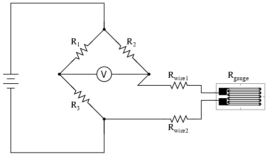
The strain gauge's resistance (Rgauge) is not the only resistance being measured: the wire resistances Rwire1 and Rwire2, being in series with Rgauge, also contribute to the resistance of the lower half of the rheostat arm of the bridge, and consequently contribute to the voltmeter's indication. This, of course, will be falsely interpreted by the meter as physical strain on the gauge.
While this effect cannot be completely eliminated in this configuration, it can be minimized with the addition of a third wire, connecting the right side of the voltmeter directly to the upper wire of the strain gauge:
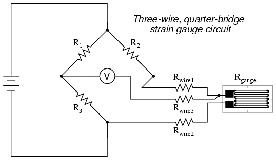
Because the third wire carries practically no current (due to the voltmeter's extremely high internal resistance), its resistance will not drop any substantial amount of voltage. Notice how the resistance of the top wire (Rwire1) has been "bypassed" now that the voltmeter connects directly to the top terminal of the strain gauge, leaving only the lower wire's resistance (Rwire2) to contribute any stray resistance in series with the gauge. Not a perfect solution, of course, but twice as good as the last circuit!
There is a way, however, to reduce wire resistance error far beyond the method just described, and also help mitigate another kind of measurement error due to temperature. An unfortunate characteristic of strain gauges is that of resistance change with changes in temperature. This is a property common to all conductors, some more than others. Thus, our quarter-bridge circuit as shown (either with two or with three wires connecting the gauge to the bridge) works as a thermometer just as well as it does a strain indicator. If all we want to do is measure strain, this is not good. We can transcend this problem, however, by using a "dummy" strain gauge in place of R2, so that both elements of the rheostat arm will change resistance in the same proportion when temperature changes, thus canceling the effects of temperature change:
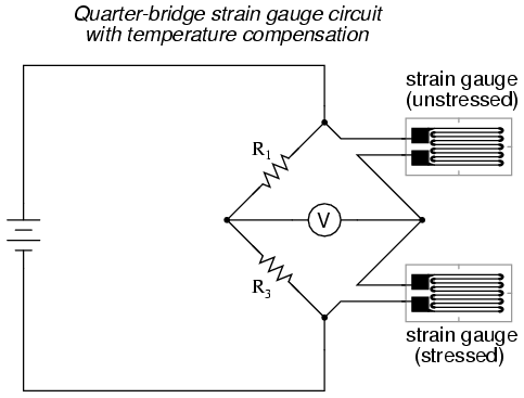
Resistors R1 and R3 are of equal resistance value, and the strain gauges are identical to one another. With no applied force, the bridge should be in a perfectly balanced condition and the voltmeter should register 0 volts. Both gauges are bonded to the same test specimen, but only one is placed in a position and orientation so as to be exposed to physical strain (the active gauge). The other gauge is isolated from all mechanical stress, and acts merely as a temperature compensation device (the"dummy" gauge). If the temperature changes, both gauge resistances will change by the same percentage, and the bridge's state of balance will remain unaffected. Only a differential resistance (difference of resistance between the two strain gauges) produced by physical force on the test specimen can alter the balance of the bridge.
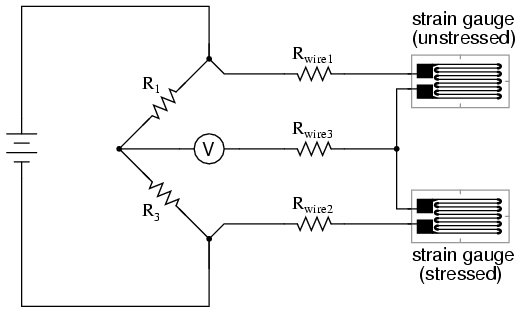
Wire resistance doesn't impact the accuracy of the circuit as much as before, because the wires connecting both strain gauges to the bridge are approximately equal length. Therefore, the upper and lower sections of the bridge's rheostat arm contain approximately the same amount of stray resistance, and their effects tend to cancel:
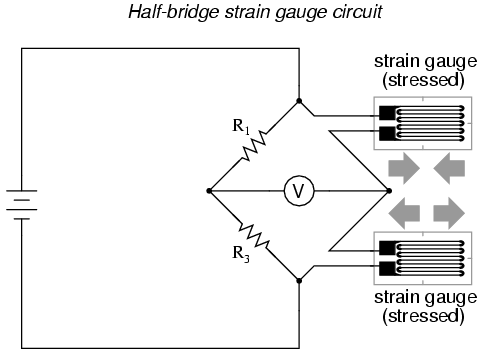
Even though there are now two strain gauges in the bridge circuit, only one is responsive to mechanical strain, and thus we would still refer to this arrangement as a quarter-bridge. However, if we were to take the upper strain gauge and position it so that it is exposed to the opposite force as the lower gauge (i.e. when the upper gauge is compressed, the lower gauge will be stretched, and vice versa), we will have both gauges responding to strain, and the bridge will be more responsive to applied force. This utilization is known as a half-bridge. Since both strain gauges will either increase or decrease resistance by the same proportion in response to changes in temperature, the effects of temperature change remain canceled and the circuit will suffer minimal temperature-induced measurement error:
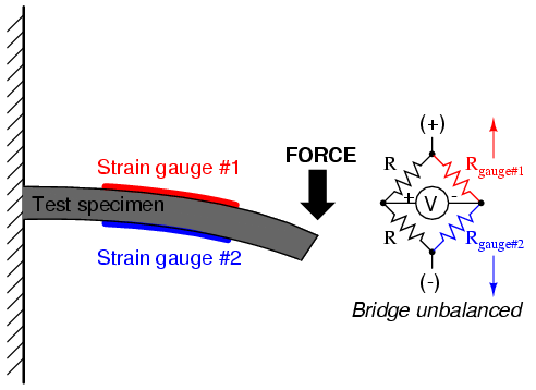
An example of how a pair of strain gauges may be bonded to a test specimen so as to yield this effect is illustrated here:
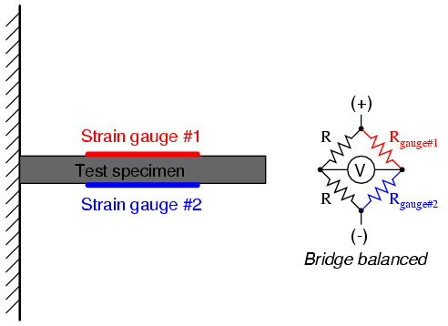
With no force applied to the test specimen, both strain gauges have equal resistance and the bridge circuit is balanced. However, when a downward force is applied to the free end of the specimen, it will bend downward, stretching gauge #1 and compressing gauge #2 at the same time:
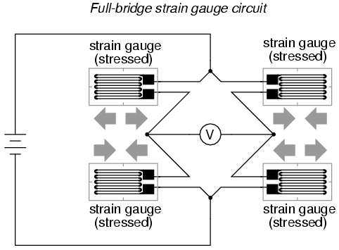
In applications where such complementary pairs of strain gauges can be bonded to the test specimen, it may be advantageous to make all four elements of the bridge "active" for even greater sensitivity. This is called a full-bridge circuit:
Both half-bridge and full-bridge configurations grant greater sensitivity over the quarter-bridge circuit, but often it is not possible to bond complementary pairs of strain gauges to the test specimen. Thus, the quarter-bridge circuit is frequently used in strain measurement systems.
When possible, the full-bridge configuration is the best to use. This is true not only because it is more sensitive than the others, but because it is linear while the others are not. Quarter-bridge and half-bridge circuits provide an output (imbalance) signal that is only approximately proportional to applied strain gauge force. Linearity, or proportionality, of these bridge circuits is best when the amount of resistance change due to applied force is very small compared to the nominal resistance of the gauge(s). With a full-bridge, however, the output voltage is directly proportional to applied force, with no approximation (provided that the change in resistance caused by the applied force is equal for all four strain gauges!).
Unlike the Wheatstone and Kelvin bridges, which provide measurement at a condition of perfect balance and therefore function irrespective of source voltage, the amount of source (or "excitation") voltage matters in an unbalanced bridge like this. Therefore, strain gauge bridges are rated in millivolts of imbalance produced per volt of excitation, per unit measure of force. A typical example for a strain gauge of the type used for measuring force in industrial environments is 15 mV/V at 1000 pounds. That is, at exactly 1000 pounds applied force (either compressive or tensile), the bridge will be unbalanced by 15 millivolts for every volt of excitation voltage. Again, such a figure is precise if the bridge circuit is full-active (four active strain gauges, one in each arm of the bridge), but only approximate for half-bridge and quarter-bridge arrangements.
Strain gauges may be purchased as complete units, with both strain gauge elements and bridge resistors in one housing, sealed and encapsulated for protection from the elements, and equipped with mechanical fastening points for attachment to a machine or structure. Such a package is typically called a load cell.
Like many of the other topics addressed in this chapter, strain gauge systems can become quite complex, and a full dissertation on strain gauges would be beyond the scope of this book.
- REVIEW:
- A strain gauge is a thin strip of metal designed to measure mechanical load by changing resistance when stressed (stretched or compressed within its elastic limit).
- Strain gauge resistance changes are typically measured in a bridge circuit, to allow for precise measurement of the small resistance changes, and to provide compensation for resistance variations due to temperature.
Examine the following specific resistance table for various metals:
Of the metals shown, which is the best conductor of electricity? Which is the worst? What do you notice about the resistivity of these metals as temperature is increased from 32oF to 75 oF?
Metal type ρ in Ω · cmil / ft @ 32oF ρ in Ω · cmil / ft @ 75oF
Zinc (very pure) 34.595 37.957
Tin (pure) 78.489 86.748
Copper (pure annealed) 9.390 10.351
Copper (hard-drawn) 9.810 10.745
Copper (annealed) 9.590 10.505
Platinum (pure) 65.670 71.418
Silver (pure annealed) 8.831 9.674
Nickel 74.128 85.138
Steel (wire) 81.179 90.150
Iron (approx. pure) 54.529 62.643
Gold (99.9 % pure) 13.216 14.404
Aluminum (99.5 % pure) 15.219 16.758
Of the metals shown, which is the best conductor of electricity? Which is the worst? What do you notice about the resistivity of these metals as temperature is increased from 32oF to 75 oF?
Calculate the amount of power delivered to the load resistor in this circuit:
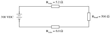
Also, calculate the amount of power that would be delivered to the load resistor if the wires were superconducting (Rwire = 0.0 Ω).
Also, calculate the amount of power that would be delivered to the load resistor if the wires were superconducting (Rwire = 0.0 Ω).
Suppose a power system were delivering AC power to a resistive load drawing 150 amps:

Calculate the load voltage, load power dissipation, the power dissipated by the wire resistance (Rwire), and the overall power efficiency, indicated by the Greek letter ëta" (η = [(Pload)/(Psource)]).
Now, suppose we were to re-design both the generator and the load to operate at 2400 volts instead of 240 volts. This ten-fold increase in voltage allows just one-tenth the current to convey the same amount of power. Rather than replace all the wire with different wire, we decide to use the exact same wire as before, having the exact same resistance (0.1 Ω per length) as before. Re-calculate load voltage, load power, wasted power, and overall efficiency of this (higher voltage) system:

Calculate the load voltage, load power dissipation, the power dissipated by the wire resistance (Rwire), and the overall power efficiency, indicated by the Greek letter ëta" (η = [(Pload)/(Psource)]).
- Eload =
- Pload =
- Plines =
- η =
Now, suppose we were to re-design both the generator and the load to operate at 2400 volts instead of 240 volts. This ten-fold increase in voltage allows just one-tenth the current to convey the same amount of power. Rather than replace all the wire with different wire, we decide to use the exact same wire as before, having the exact same resistance (0.1 Ω per length) as before. Re-calculate load voltage, load power, wasted power, and overall efficiency of this (higher voltage) system:
- Eload =
- Pload =
- Plines =
- η =
The efficiency (η) of a simple power system with losses occurring over the wires is a function of circuit current, wire resistance, and total source power:

A simple formula for calculating efficiency is given here:
Where,
Psource = the power output by the voltage source, in watts (W)
I = the circuit current, in amperes (A)
R = the total wire resistance (Rwire1 + Rwire2), in ohms (Ω)
Algebraically manipulate this equation to solve for wire resistance (R) in terms of all the other variables, and then calculate the maximum amount of allowable wire resistance for a power system where a source outputting 200 kW operates at a circuit current of 48 amps, at a minimum efficiency of 90%.
A simple formula for calculating efficiency is given here:
|
Where,
Psource = the power output by the voltage source, in watts (W)
I = the circuit current, in amperes (A)
R = the total wire resistance (Rwire1 + Rwire2), in ohms (Ω)
Algebraically manipulate this equation to solve for wire resistance (R) in terms of all the other variables, and then calculate the maximum amount of allowable wire resistance for a power system where a source outputting 200 kW operates at a circuit current of 48 amps, at a minimum efficiency of 90%.
Thermocouples
An interesting phenomenon applied in the field of instrumentation is the Seebeck effect, which is the production of a small voltage across the length of a wire due to a difference in temperature along that wire. This effect is most easily observed and applied with a junction of two dissimilar metals in contact, each metal producing a different Seebeck voltage along its length, which translates to a voltage between the two (unjoined) wire ends. Most any pair of dissimilar metals will produce a measurable voltage when their junction is heated, some combinations of metals producing more voltage per degree of temperature than others:

The Seebeck effect is fairly linear; that is, the voltage produced by a heated junction of two wires is directly proportional to the temperature. This means that the temperature of the metal wire junction can be determined by measuring the voltage produced. Thus, the Seebeck effect provides for us an electric method of temperature measurement.
When a pair of dissimilar metals are joined together for the purpose of measuring temperature, the device formed is called a thermocouple. Thermocouples made for instrumentation use metals of high purity for an accurate temperature/voltage relationship (as linear and as predictable as possible).
Seebeck voltages are quite small, in the tens of millivolts for most temperature ranges. This makes them somewhat difficult to measure accurately. Also, the fact that any junction between dissimilar metals will produce temperature-dependent voltage creates a problem when we try to connect the thermocouple to a voltmeter, completing a circuit:

The second iron/copper junction formed by the connection between the thermocouple and the meter on the top wire will produce a temperature-dependent voltage opposed in polarity to the voltage produced at the measurement junction. This means that the voltage between the voltmeter's copper leads will be a function of the difference in temperature between the two junctions, and not the temperature at the measurement junction alone. Even for thermocouple types where copper is not one of the dissimilar metals, the combination of the two metals joining the copper leads of the measuring instrument forms a junction equivalent to the measurement junction:

This second junction is called the reference or cold junction, to distinguish it from the junction at the measuring end, and there is no way to avoid having one in a thermocouple circuit. In some applications, a differential temperature measurement between two points is required, and this inherent property of thermocouples can be exploited to make a very simple measurement system.

However, in most applications the intent is to measure temperature at a single point only, and in these cases the second junction becomes a liability to function.
Compensation for the voltage generated by the reference junction is typically performed by a special circuit designed to measure temperature there and produce a corresponding voltage to counter the reference junction's effects. At this point you may wonder, "If we have to resort to some other form of temperature measurement just to overcome an idiosyncrasy with thermocouples, then why bother using thermocouples to measure temperature at all? Why not just use this other form of temperature measurement, whatever it may be, to do the job?" The answer is this: because the other forms of temperature measurement used for reference junction compensation are not as robust or versatile as a thermocouple junction, but do the job of measuring room temperature at the reference junction site quite well. For example, the thermocouple measurement junction may be inserted into the 1800 degree (F) flue of a foundry holding furnace, while the reference junction sits a hundred feet away in a metal cabinet at ambient temperature, having its temperature measured by a device that could never survive the heat or corrosive atmosphere of the furnace.
The voltage produced by thermocouple junctions is strictly dependent upon temperature. Any current in a thermocouple circuit is a function of circuit resistance in opposition to this voltage (I=E/R). In other words, the relationship between temperature and Seebeck voltage is fixed, while the relationship between temperature and current is variable, depending on the total resistance of the circuit. With heavy enough thermocouple conductors, currents upwards of hundreds of amps can be generated from a single pair of thermocouple junctions! (I've actually seen this in a laboratory experiment, using heavy bars of copper and copper/nickel alloy to form the junctions and the circuit conductors.)
For measurement purposes, the voltmeter used in a thermocouple circuit is designed to have a very high resistance so as to avoid any error-inducing voltage drops along the thermocouple wire. The problem of voltage drop along the conductor length is even more severe here than with the DC voltage signals discussed earlier, because here we only have a few millivolts of voltage produced by the junction. We simply cannot afford to have even a single millivolt of drop along the conductor lengths without incurring serious temperature measurement errors.
Ideally, then, current in a thermocouple circuit is zero. Early thermocouple indicating instruments made use of null-balance potentiometric voltage measurement circuitry to measure the junction voltage. The early Leeds & Northrup "Speedomax" line of temperature indicator/recorders were a good example of this technology. More modern instruments use semiconductor amplifier circuits to allow the thermocouple's voltage signal to drive an indication device with little or no current drawn in the circuit.
Thermocouples, however, can be built from heavy-gauge wire for low resistance, and connected in such a way so as to generate very high currents for purposes other than temperature measurement. One such purpose is electric power generation. By connecting many thermocouples in series, alternating hot/cold temperatures with each junction, a device called a thermopile can be constructed to produce substantial amounts of voltage and current:

With the left and right sets of junctions at the same temperature, the voltage at each junction will be equal and the opposing polarities would cancel to a final voltage of zero. However, if the left set of junctions were heated and the right set cooled, the voltage at each left junction would be greater than each right junction, resulting in a total output voltage equal to the sum of all junction pair differentials. In a thermopile, this is exactly how things are set up. A source of heat (combustion, strong radioactive substance, solar heat, etc.) is applied to one set of junctions, while the other set is bonded to a heat sink of some sort (air- or water-cooled). Interestingly enough, as electrons flow through an external load circuit connected to the thermopile, heat energy is transferred from the hot junctions to the cold junctions, demonstrating another thermo-electric phenomenon: the so-called Peltier Effect (electric current transferring heat energy).
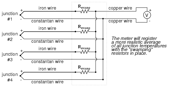
Another application for thermocouples is in the measurement of average temperature between several locations. The easiest way to do this is to connect several thermocouples in parallel with each other. The millivolt signal produced by each thermocouple will average out at the parallel junction point. The voltage differences between the junctions drop along the resistances of the thermocouple wires:

Unfortunately, though, the accurate averaging of these Seebeck voltage potentials relies on each thermocouple's wire resistances being equal. If the thermocouples are located at different places and their wires join in parallel at a single location, equal wire length will be unlikely. The thermocouple having the greatest wire length from point of measurement to parallel connection point will tend to have the greatest resistance, and will therefore have the least effect on the average voltage produced.
To help compensate for this, additional resistance can be added to each of the parallel thermocouple circuit branches to make their respective resistances more equal. Without custom-sizing resistors for each branch (to make resistances precisely equal between all the thermocouples), it is acceptable to simply install resistors with equal values, significantly higher than the thermocouple wires' resistances so that those wire resistances will have a much smaller impact on the total branch resistance. These resistors are called swamping resistors, because their relatively high values overshadow or "swamp" the resistances of the thermocouple wires themselves:
Because thermocouple junctions produce such low voltages, it is imperative that wire connections be very clean and tight for accurate and reliable operation. Also, the location of the reference junction (the place where the dissimilar-metal thermocouple wires join to standard copper) must be kept close to the measuring instrument, to ensure that the instrument can accurately compensate for reference junction temperature. Despite these seemingly restrictive requirements, thermocouples remain one of the most robust and popular methods of industrial temperature measurement in modern use.
- REVIEW:
- The Seebeck Effect is the production of a voltage between two dissimilar, joined metals that is proportional to the temperature of that junction.
- In any thermocouple circuit, there are two equivalent junctions formed between dissimilar metals. The junction placed at the site of intended measurement is called the measurementjunction, while the other (single or equivalent) junction is called the reference junction.
- Two thermocouple junctions can be connected in opposition to each other to generate a voltage signal proportional to differential temperature between the two junctions. A collection of junctions so connected for the purpose of generating electricity is called a thermopile.
- When electrons flow through the junctions of a thermopile, heat energy is transferred from one set of junctions to the other. This is known as the Peltier Effect.
- Multiple thermocouple junctions can be connected in parallel with each other to generate a voltage signal representing the average temperature between the junctions. "Swamping" resistors may be connected in series with each thermocouple to help maintain equality between the junctions, so the resultant voltage will be more representative of a true average temperature.
- It is imperative that current in a thermocouple circuit be kept as low as possible for good measurement accuracy. Also, all related wire connections should be clean and tight. Mere millivolts of drop at any place in the circuit will cause substantial measurement errors.
Vezi și
Romania traiește , încă , din inertia bogățiilor create in Epoca Comunistă
Europa privită din viitor
Hrana vie
Planurile in derulare sunt o munca in progres, veche de sute de ani
Duda a pus mâna pe Casa Regală
Nu poti multiplica bogatia divizand-o !
Evolutia Laptop - Cântărea 5,44 kg
În vremea monarhiei, taranii romani reprezentau 90% din populatie si nu aveau drept de vot.
Miracolul din Noua Zeelandă - LYPRINOL
Locul unde Cerul se uneste cu Pamantul
Fii propriul tău nutriționist
Maya ramane o civilizatie misterioasa
Slăbești daca esti motivat
Serbet de ciocolata
Medicament retras - folosit în diabet
Brexit-ul - Spaima Europei
Virusul Misterios
Sistemele solare - apă caldă
Aparitia starii de insolventa
TRUMP ESTE PRESEDINTE
Despre islamizarea Europei. O publicăm integral. Și fără comentarii.
Tavalugul Marelui Razboi - Globaliyarea - Asasinii Economici
Niciun comentariu:
Trimiteți un comentariu