A DIY photoplethysmographic sensor for measuring heart rate.
Theory and Schematic
When I first built the Heart rate measurement through fingertip project, the infrared LED and photodiode used for finger photoplethysmography were actually from salvaged parts, and therefore, I could not provide specifications for them in the article. As a result of that it takes quite a bit of time to replicate that project with a different set of IR LED and photodiode as the values of the current limiting and biasing resistors may have to be changed for the new sensor to work properly. Today, I am going to talk about a revised version of the same project but with all the components specified this time. The new version uses theTCRT1000 reflective optical sensor for photoplethysmography. The use of TCRT100 simplifies the build process of the sensor part of the project as both the infrared light emitter diode and the detector are arranged side by side in a leaded package, thus blocking the surrounding ambient light, which could otherwise affect the sensor performance. I have also designed a printed circuit board for it, which carries both sensor and signal conditioning unit. I have named the board “Easy Pulse” and its output is a digital pulse which is synchronous with the heart beat. The output pulse can be fed to either an ADC channel or a digital input pin of a microcontroller for further processing and retrieving the heart rate in beats per minute (BPM).

Easy Pulse sensor
Theory
This project is based on the principle of photoplethysmography (PPG) which is a non-invasive method of measuring the variation in blood volume in tissues using a light source and a detector. Since the change in blood volume is synchronous to the heart beat, this technique can be used to calculate the heart rate. Transmittance and reflectance are two basic types of photoplethysmography.
For the transmittance PPG, a light source is emitted in to the tissue and a light detector is placed in the opposite side of the tissue to measure the resultant light. Because of the limited penetration depth of the light through organ tissue, the transmittance PPG is applicable to a restricted body part, such as the finger or the ear lobe. However, in the reflectance PPG, the light source and the light detector are both placed on the same side of a body part. The light is emitted into the tissue and the reflected light is measured by the detector. As the light doesn’t have to penetrate the body, the reflectance PPG can be applied to any parts of human body. In either case, the detected light reflected from or transmitted through the body part will fluctuate according to the pulsatile blood flow caused by the beating of the heart.
Afaceri online
PC Computer
Locuinta - O investitie necesara
De la prietenii niștri RELIGIE
LITERATURA și CREDINTA
Economico - Sociale
Politici Fiscale , Sociale
Situatia ECONOMICO-SOCIALA
Stiinta si tehnica
For the transmittance PPG, a light source is emitted in to the tissue and a light detector is placed in the opposite side of the tissue to measure the resultant light. Because of the limited penetration depth of the light through organ tissue, the transmittance PPG is applicable to a restricted body part, such as the finger or the ear lobe. However, in the reflectance PPG, the light source and the light detector are both placed on the same side of a body part. The light is emitted into the tissue and the reflected light is measured by the detector. As the light doesn’t have to penetrate the body, the reflectance PPG can be applied to any parts of human body. In either case, the detected light reflected from or transmitted through the body part will fluctuate according to the pulsatile blood flow caused by the beating of the heart.
The following picture shows a basic reflectance PPG probe to extract the pulse signal from the fingertip. A subject’s finger is illuminated by an infrared light-emitting diode. More or less light is absorbed, depending on the tissue blood volume. Consequently, the reflected light intensity varies with the pulsing of the blood with heart beat. A plot for this variation against time is referred to be a photoplethysmographic or PPG signal.

Finger photoplethysmography (reflectance approach)
The PPG signal has two components, frequently referred to as AC and DC. The AC component is mainly caused by pulsatile changes in arterial blood volume, which is synchronous with the heart beat. So, the AC component can be used as a source of heart rate information. This AC component is superimposed onto a large DC component that relates to the tissues and to the average blood volume. The DC component must be removed to measure the AC waveform with a high signal-to-noise ratio. Since the useful AC signal is only a very small portion of the whole signal, an effective amplification circuit is also required to extract desired information from it.
Circuit diagram
The sensor used in this project is TCRT1000, which is a reflective optical sensor with both the infrared light emitter and phototransistor placed side by side and are enclosed inside a leaded package so that there is minimum effect of surrounding visible light. The circuit diagram below shows the external biasing circuit for the TCRT1000 sensor. Pulling the Enable pin high will turn the IR emitter LED on and activate the sensor. A fingertip placed over the sensor will act as a reflector of the incident light. The amount of light reflected back from the fingertip is monitored by the phototransistor.

TCRT1000 used for sensing pulse from fingertip
The output (VSENSOR) from the sensor is a periodic physiological waveform attributed to small variations in the reflected IR light which is caused by the pulsatile tissue blood volume inside the finger. The waveform is, therefore, synchronous with the heart beat. The following circuit diagram describes the first stage of the signal conditioning which will suppress the large DC component and boost the weak pulsatile AC component, which carries the required information.

First stage of signal conditioning
In the circuit shown above, the sensor output is first passed through a RC high-pass filter (HPF) to get rid of the DC component. The cut-off frequency of the HPF is set to 0.7 Hz. Next stage is an active low-pass filter (LPF) that is made of an Op-Amp circuit. The gain and the cut-off frequency of the LPF are set to 101 and 2.34 Hz, respectively. Thus the combination of the HPF and LPF helps to remove unwanted DC signal and high frequency noise including 60 Hz (50 Hz in some countries) mains interference, while amplifying the low amplitude pulse signal (AC component) 101 times.
The output from the first signal conditioning stage goes to a similar HPF/LPF combination for further filtering and amplification (shown below). So, the total voltage gain achieved from the two cascaded stages is 101*101 = 10201. The two stages of filtering and amplification converts the input PPG signals to near TTL pulses and they are synchronous with the heart beat. The frequency (f) of these pulses is related to the heart rate (BPM) as,
Beats per minute (BPM) = 60×f
A 5K potentiometer is placed at the output of the first signal conditioning stage in case the total gain of the two stages is required to be less than 10201. An LED connected to the output of the second stage of signal conditioning will blink when a heart beat is detected. The final stage of the instrumentation constitutes a simple non-inverting buffer to lower the output impedance. This is helpful if an ADC channel of a microcontroller is used to read the amplified PPG signal.

Second stage of signal conditioning
The operational amplifiers used in the instrumentation circuit described above are from the MCP6004 IC, which has got four general purpose Op-Amps offering rail-to-rail input and output over the 1.8 to 6V operating range. The picture below shows an assembled Easy Pulse board designed using the above circuit.
Instead of fixing on the board, the TCRT1000 sensor can also be wired to the board through header pins and jumpers. This way you have more flexibility in using the sensor. You can hold the sensor between two fingers or you can face it down on the skin on your palm, and so on.

Easy Pulse with sensor wire to the board through jumpers
The board operates from 3-5.5V and therefore, it can be used with both 3.3V and 5.0V microcontroller families.
Translation in Romanian
Pulse ușor: Un senzor de DIY photoplethysmographic pentru masurarea ritmului cardiac. Partea 1 - Teoria și Schema
Când am construit prima măsurare a ritmului cardiac prin degetului proiect, cu LED-uri infraroșu și fotodiodă, utilizate pentru fotopletismografie deget au fost de fapt de la piese recuperate, și, prin urmare, nu am putut oferi specificațiile pentru ei în articol. Ca urmare a că este nevoie de destul de un pic de timp pentru a reproduce acest proiect cu un set diferit de IR LED-uri și fotodiodă, în calitate de valorile rezistoarelor curent de limitare și polarizare ar putea fi schimbate pentru noul senzor pentru a funcționa corect. Astăzi, am de gând să vorbesc despre o versiune revizuită a proiectului fel, dar cu toate componentele specificate de data asta. Noua versiune foloseste TCRT1000 senzor reflexiv optic pentru fotopletismografie. Utilizarea TCRT100 simplifică procesul de construire a senzorului parte a proiectului atât ca diodă infraroșu emițător de lumină și detectorul sunt aranjate una lângă alta într-un pachet cu tetraetil de plumb, blocând astfel de lumină ambientală din jur, care ar putea afecta în vreun fel performanța senzorului. Am proiectat, de asemenea, o placa de circuit imprimat pentru ea, care poartă atât senzorul de semnal și unitatea de climatizare. Am numit bord "Pulse Easy" și producția sa este un puls digitală, care este sincronă cu ritmul inimii. Impuls de ieșire poate fi alimentat fie un canal ADC sau un pin de intrare digitală a unui microcontroler pentru continuarea prelucrarea și recuperarea ritmului cardiac în bătăi pe minut (BPM).
Acest proiect se bazează pe principiul fotopletismografie (PPG), care este o metoda non-invaziva de măsurare Variația în volum de sange in tesuturi folosind o sursa de lumina si un detector. Deoarece modificarea volumului de sange este sincronă a bătăilor inimii, această tehnică poate fi utilizată pentru a calcula rata de inima. Transmisie și reflexie sunt două tipuri de bază de fotopletismografie. Pentru transmisie PPG, o sursa de lumina este emisă în a țesuturilor și un detector de lumina este plasat în partea opusă a țesutului pentru a măsura lumina rezultantă. Din cauza adâncimii de penetrare limitată a luminii prin tesuturi de organe, de transmisie PPG este aplicabilă o parte a corpului restrânsă, cum ar fi degetul sau lobul urechii. Cu toate acestea, în PPG reflexiei, sursa de lumină și detector de lumină sunt atât plasate pe aceeași parte a unei părți a corpului. Lumina este emisă în țesuturi și lumina reflectata este măsurată prin detector. Așa cum lumina nu are de a penetra corpul, PPG reflexie poate fi aplicat la orice parte a corpului uman. În ambele cazuri, lumina reflectata de detectat sau transmise prin intermediul parte a corpului va fluctua în funcție de fluxul de sange pulsand cauzate de bataie a inimii.
Imaginea de mai jos prezintă o bază de reflexie PPG sonda pentru a extrage semnalul de impuls de la vârful degetului. Degetul Un subiect este iluminat de o lumina infrarosie-emitting diode. Lumină mult sau mai puțin este absorbit, în funcție de volumul de sânge țesut. Prin urmare, intensitatea luminii reflectate variază în funcție de vibrantă a arteriale cu bătăi cardiace. Un complot pentru această variație în funcție de timp se face referire să fie un semnal de photoplethysmographic sau PPG.
Diagrama circuitului
Senzorul utilizat în acest proiect este de TCRT1000, care este un senzor reflexiv optic cu atât emițător de lumină infraroșie și fototranzistor partea plasate de către parte, și sunt închise în interiorul unui pachet de plumb, astfel că nu există un efect minim de incadrand luminii vizibile. Diagrama circuitului de mai jos prezinta circuitul exterior biasing pentru senzorul TCRT1000. Trăgând Activare pinul de mare va transforma emitator IR LED și de a activa senzorul. Un vârful plasat peste senzorul va acționa ca un reflector al luminii incidente. Cantitatea de lumină reflectată înapoi de la vârful degetului este monitorizată de către fototranzistor.
Prima etapă de condiționare de semnal
În circuitul de mai sus, ieșirea senzorului este primul trecut printr-un RC high-pass filtru (HPF) pentru a scăpa de componente DC. Frecvența limită a HPF este setată la 0,7 Hz. Următoarea etapă este un activ filtru low-pass (LPF), care este format dintr-un circuit Op-Amp. Câștig și frecvența-limită al LPF sunt setate la 101 și 2.34 Hz, respectiv. Astfel, combinația de HPF si LPF ajută la eliminarea semnal nedorit DC și zgomotul de înaltă frecvență, inclusiv 60 Hz (50 Hz în unele țări) alimentare interferențe, în timp ce amplificarea semnalului puls scăzut amplitudine (AC componenta) 101 de ori.
De ieșire din prima etapă condiționat de semnal merge la o similară HPF / LPF combinatie de filtrare în continuare și amplificare (de mai jos). Deci, amplificarea în tensiune totală realizată de cele două etape cascadă este de 101 * 101 = 10201. Cele două etape de filtrare și amplificare convertește semnalele de intrare TTL PPG la apropiat impulsuri si sunt sincrone cu bătăi cardiace. Frecvența (f) din aceste impulsuri este legată de frecvența cardiacă (BPM), ca,
A doua etapă de condiționare de semnal
Cele amplificatoare operaționale utilizate în circuitul instrumentelor descrise mai sus sunt de la MCP6004IC, care are patru General Purpose Op-amper oferă feroviar-la-feroviar de intrare și ieșire pe gama de funcționare 1.8 la 6V. Imaginea de mai jos prezinta o placa de asamblat Pulsul Easy proiectate folosind circuitul de mai sus.
În loc de fixare pe bord, senzorul poate fi, de asemenea, TCRT1000 fir la bord prin pinii antet și pulovere.În acest fel aveți o mai mare flexibilitate în utilizarea senzorului. Aveți posibilitatea să țineți senzorul între două degete sau puteți să-l cu fața în jos pe pielea de pe palma, și așa mai departe.
Pulse ușor cu sârmă senzor la bord prin jumperi
Bord opereaza la 3-5.5V și, prin urmare, acesta poate fi folosit cu familiile microcontrolere atât 3.3V 5.0V si.
Imaginea de mai jos prezintă o bază de reflexie PPG sonda pentru a extrage semnalul de impuls de la vârful degetului. Degetul Un subiect este iluminat de o lumina infrarosie-emitting diode. Lumină mult sau mai puțin este absorbit, în funcție de volumul de sânge țesut. Prin urmare, intensitatea luminii reflectate variază în funcție de vibrantă a arteriale cu bătăi cardiace. Un complot pentru această variație în funcție de timp se face referire să fie un semnal de photoplethysmographic sau PPG.
Degetul fotopletismografie (abordare de reflexie)
Semnalul PPG are două componente, frecvent menționate în continuare AC si DC. Componenta CA este cauzată în principal de modificările pulseaza in volum de sânge arterial, care este sincronă cu ritmul inimii.Deci, componenta CA poate fi folosit ca o sursă de informații ritmului cardiac. Această componentă AC este suprapus pe o componentă DC mare, care se referă la țesuturi și volumul de sânge mediu.Componenta DC trebuie să fie eliminate pentru a măsura forma de undă de curent alternativ, cu un nivel ridicat semnal-zgomot. Deoarece util semnal AC este doar o parte foarte mică a semnalului de ansamblu, un circuit de amplificare eficient este, de asemenea, necesară pentru a extrage informațiile dorite de la ea.Diagrama circuitului
Senzorul utilizat în acest proiect este de TCRT1000, care este un senzor reflexiv optic cu atât emițător de lumină infraroșie și fototranzistor partea plasate de către parte, și sunt închise în interiorul unui pachet de plumb, astfel că nu există un efect minim de incadrand luminii vizibile. Diagrama circuitului de mai jos prezinta circuitul exterior biasing pentru senzorul TCRT1000. Trăgând Activare pinul de mare va transforma emitator IR LED și de a activa senzorul. Un vârful plasat peste senzorul va acționa ca un reflector al luminii incidente. Cantitatea de lumină reflectată înapoi de la vârful degetului este monitorizată de către fototranzistor.
TCRT1000 utilizat pentru detectarea pulsului de la vârful degetului
De ieșire ( V SENZOR ) de la senzorul este o formă de undă periodică fiziologic atribuite mici variații în lumina reflectată IR, care este cauzată de volumul de sange pulsand in interiorul tesutului degetul. Undă este, prin urmare, sincron cu bataile inimii. Diagrama circuitului de mai jos descrie prima etapă a condiționare de semnal care va suprima componenta DC de mare și să stimuleze slab pulsand componenta de curent alternativ, care transportă informațiile cerute.Prima etapă de condiționare de semnal
De ieșire din prima etapă condiționat de semnal merge la o similară HPF / LPF combinatie de filtrare în continuare și amplificare (de mai jos). Deci, amplificarea în tensiune totală realizată de cele două etape cascadă este de 101 * 101 = 10201. Cele două etape de filtrare și amplificare convertește semnalele de intrare TTL PPG la apropiat impulsuri si sunt sincrone cu bătăi cardiace. Frecvența (f) din aceste impulsuri este legată de frecvența cardiacă (BPM), ca,
Bătăi pe minut (BPM) = 60 × f
Un potențiometru 5K este plasat la ieșirea din prima etapă condiționat de semnal în cazul în care câștigul totală a celor două etape trebuie să fie mai mică de 10201. Un LED conectat la ieșirea de-a doua etapă de condiționare de semnal va clipi atunci când un ritm cardiac este detectat. Etapa finală a instrumentelor constituie o simplă ne-inversoare tampon pentru a reduce impedanța de ieșire. Acest lucru este util în cazul în care un canal ADC de un microcontroler este utilizat pentru a citi semnalul amplificat PPG.A doua etapă de condiționare de semnal
În loc de fixare pe bord, senzorul poate fi, de asemenea, TCRT1000 fir la bord prin pinii antet și pulovere.În acest fel aveți o mai mare flexibilitate în utilizarea senzorului. Aveți posibilitatea să țineți senzorul între două degete sau puteți să-l cu fața în jos pe pielea de pe palma, și așa mai departe.
Pulse ușor cu sârmă senzor la bord prin jumperi
http://www.radiolocman.com


Heart rate measurement from fingertip
Heart rate measurement indicates the soundness of the human cardiovascular system. This project demonstrates a technique to measure the heart rate by sensing the change in blood volume in a finger artery while the heart is pumping the blood. It consists of an infrared LED that transmits an IR signal through the fingertip of the subject, a part of which is reflected by the blood cells. The reflected signal is detected by a photo diode sensor. The changing blood volume with heartbeat results in a train of pulses at the output of the photo diode, the magnitude of which is too small to be detected directly by a microcontroller. Therefore, a two-stage high gain, active low pass filter is designed using two Operational Amplifiers (OpAmps) to filter and amplify the signal to appropriate voltage level so that the pulses can be counted by a microcontroller. The heart rate is displayed on a 3 digit seven segment display. The microcontroller used in this project is PIC16F628A.
Theory
Heart rate is the number of heartbeats per unit of time and is usually expressed in beats per minute (bpm). In adults, a normal heart beats about 60 to 100 times a minute during resting condition. The resting heart rate is directly related to the health and fitness of a person and hence is important to know. You can measure heart rate at any spot on the body where you can feel a pulse with your fingers. The most common places are wrist and neck. You can count the number of pulses within a certain interval (say 15 sec), and easily determine the heart rate in bpm.
This project describes a microcontroller based heart rate measuement system that uses optical sensors to measure the alteration in blood volume at fingertip with each heart beat. The sensor unit consists of an infrared light-emitting-diode (IR LED) and a photodiode, placed side by side as shown below. The IR diode transmits an infrared light into the fingertip (placed over the sensor unit), and the photodiode senses the portion of the light that is reflected back. The intensity of reflected light depends upon the blood volume inside the fingertip. So, each heart beat slightly alters the amount of reflected infrared light that can be detected by the photodiode. With a proper signal conditioning, this little change in the amplitude of the reflected light can be converted into a pulse. The pulses can be later counted by the microcontroller to determine the heart rate.
Circuit Diagram
The signal conditioning circuit consists of two identical active low pass filters with a cut-off frequency of about 2.5 Hz. This means the maximum measurable heart rate is about 150 bpm. The operational amplifier IC used in this circuit is MCP602, a dual OpAmp chip from Microchip. It operates at a single power supply and provides rail-to-rail output swing. The filtering is necessary to block any higher frequency noises present in the signal. The gain of each filter stage is set to 101, giving the total amplification of about 10000. A 1 uF capacitor at the input of each stage is required to block the dc component in the signal. The equations for calculating gain and cut-off frequency of the active low pass filter are shown in the circuit diagram. The two stage amplifier/filter provides sufficient gain to boost the weak signal coming from the photo sensor unit and convert it into a pulse. An LED connected at the output blinks every time a heart beat is detected. The output from the signal conditioner goes to the T0CKI input of PIC16F628A.
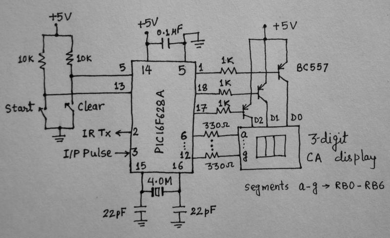
The control and display part of the circuit is shown below. The display unit comprises of a 3-digit, common anode, seven segment module that is driven using multiplexing technique. The segments a-g are driven through PORTB pins RB0-RB6, respectively. The unit’s, ten’s and hundred’s digits are multiplexed with RA2, RA1, and RA0 port pins. A tact switch input is connected to RB7 pin. This is to start the heart rate measurement. Once the start button is pressed, the microcontroller activates the IR transmission in the sensor unit for 15 sec. During this interval, the number of pulses arriving at the T0CKI input is counted. The actual heart rate would be 4 times the count value, and the resolution of measurement would be 4. You can see the IR transmission is controlled through RA3 pin of PIC16F628A. The microcontroller runs at 4.0 MHz using an external crystal. A regulated +5V power supply is derived from an external 9 V battery using an LM7805 regulator IC.
Niciun comentariu:
Trimiteți un comentariu