
For battery-powered circuits, it is easy to build an ultralow-current crystal oscillator designed around a 32.768-kHz crystal. This crystal is common for real-timeclock circuits. Because these circuits must operate at all times, achieving the lowest current draw possible is mandatory. Traditional gate-oscillator circuits – the 74HC04, for example – can draw several milliamps; the circuit shown in Figure 1 normally draws only about 5 µA. This circuit uses the Texas Instruments LPV7215MF comparator, which is housed in a five-pin SOT-23 package. The operating current for this comparator is 580 nA; the entire circuit shown in Figure 1 draws only 5 µA when running from a 3.3V supply.
Vezi și
Romania traiește , încă , din inertia bogățiilor create in Epoca Comunistă
Europa privită din viitor
Hrana vie
Planurile in derulare sunt o munca in progres, veche de sute de ani
Duda a pus mâna pe Casa Regală
Nu poti multiplica bogatia divizand-o !
Evolutia Laptop - Cântărea 5,44 kg
În vremea monarhiei, taranii romani reprezentau 90% din populatie si nu aveau drept de vot.
Miracolul din Noua Zeelandă - LYPRINOL
Locul unde Cerul se uneste cu Pamantul
Fii propriul tău nutriționist
Maya ramane o civilizatie misterioasa
Slăbești daca esti motivat
Serbet de ciocolata
Medicament retras - folosit în diabet
Brexit-ul - Spaima Europei
Virusul Misterios
Sistemele solare - apă caldă
Aparitia starii de insolventa
TRUMP ESTE PRESEDINTE
Despre islamizarea Europei. O publicăm integral. Și fără comentarii.
Tavalugul Marelui Razboi - Globaliyarea - Asasinii Economici
 | |
| Figure 1. | Traditional gate-oscillator circuits can draw several milliamps; the circuit shown normally draws only about 5 μA. |
Multiple copies of this circuit have been built and tested to confirm the 5-µA current draw. The largest portion of the 5 µA goes to the largely unavoidable operations of charging and discharging the output load capacitance. The circuit was tested using a standard 10-MΩ oscilloscope probe with about 10 pF of shunt capacitance; operating current into more capacitive loads will be higher. Table 1 breaks down the power consumption piece by piece.
Capacitive loads must be charged by the upper transistor in the active output stage of the LPV7215. To charge a capacitor to 3.3V, note the capacitor equation
Q=C×V.
This charge is transferred into the capacitance during the first half of each cycle of the 32.768-kHz oscillation. During the second half, the charge is transferred to ground. As a result, the output-stage current, i, will be
i=f×Q=f×C×V.
For 20 pF (a 10-pF scope probe plus a PCB parasitic),
i=(32.768 kHz) (20 pF) (3.3V)=2.163 µA.
From the equation above, it can be seen that additional output loading or higher operating frequencies will draw more output current. Anything that can be done to reduce the capacitive load will reduce the total current draw. Figure 2 shows an example of the test boards used to create the crystal-oscillator circuit.
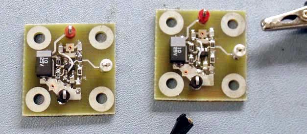 | |
| Figure 2. | Test boards of a crystal-oscillator circuit are based on the Texas Instruments LPV7215MF comparator. |
Typical LR44 alkaline button-cell batteries (Figure 3) have a capacity of 150 mAhr. With 5 µA of current draw, this clock circuit could run for about 30,000 hours, or 3.4 years.
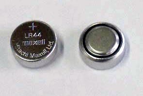 | |
| Figure 3. | Typical LR44 alkaline button-cell batteries supply 150 mAhr of capacity. |
Table 1. Loading estimates
Source
|
Supply current (μA)
|
| LPV7215MF |
0.58
|
| R1 and R2 bias |
0.33
|
| R3 |
0.083
|
| Crystal network (estimated) |
2
|
| 10-MΩ probe load |
0.165
|
| 20-pF load capacitance |
2.163
|
| Estimated total |
5.321
|
| Actual total |
5
|
Voltage-controlled oscillators
One way to achieve this goal is to replace the timing capacitor with a variable capacitor whose capacitance inversely changes with bias voltage: a varactor diode (Reference 1). For this design, theAnalog Devices AD654 voltage-to-frequency converter was considered because of its simplicity and bandwidth of at least 1 MHz (Reference 2).
 | |
| Figure 1. | The usual usage of this VCO IC is with a fixed timing capacitor, CT, at pins 6 and 7. |
Figure 1 shows a typical implementation using a fixed resistor and capacitor. For the values shown, this setup gives a frequency range of approximately 10 Hz to 30 kHz over 0 to 10V on the input. After replacing the timing capacitor with an NTE618 hyperabrupt varactor, as shown in Figure 2, the same input voltage range of 0 to 10V produced a tuning range of approximately 10 Hz to more than 1 MHz (Reference 3).
 | |
| Figure 2. | A voltage-variable capacitor (varactor) and an ac-coupled dc-bias network replace the fixed timing capacitor. |
The plot in Figure 3 compares the tuning curves of each converter configuration. Note the dramatic increase in range, but at the expense of linearity. Temperature stability will also be affected. Overall, precision is traded for tuning range, which should be acceptable in basic applications that do not require the specified precision.
 | |
| Figure 3. | Replacing the fixed timing capacitor with a voltage-variable capacitor results in a much wider tuning range. |
The hyperabrupt varactor allows large changes in frequency for small changes in bias voltage because of the large capacitance ratio. For some hyperabrupt varactors, the ratio can be as high as 15, as in the case of the NTE618, a varactor that AM receivers use. As the frequency of the converter increases with higher voltage, the capacitance decreases, which in turn increases the frequency. This combination of responses generates the wide tuning range. The 0.01-μF coupling capacitors separate the varactor bias voltage from the operation of the converter core. Light varactor biasing with high-value, 1M resistors prevents additional loading of the oscillator.
This behavior is calculable and predictable to some degree, even from the data sheets. The tuning curve for the varactor diode can be generated in Microsoft Excel. This information then can be used in the voltage-to-frequency conversion equation for the converter. For the NTE618, the approximate relationship of capacitance to voltage is expressed as
C = 800×10−10×e−0.46V.
Figure 4 shows the similarity between the calculated and measured results. The higher frequencies differ more as the varactor capacitance reduces to the order of the stray capacitance in the circuit and parts. Careful layout can minimize this issue and increase the range. | |
| Figure 4. | The calculated and measured responses are in close agreement. |
Note that at low input voltages, the varactor-based response and the fixed-capacitor converter response are nearly identical because of the varactor’s inverse exponential relationship to the voltage. One useful result of achieving this range is eliminating the need to switch between converters to extend the tuning range. You can explore other useful and interesting applications using this approach with phase-locked loops, modulators, or function generators.
Editor’s note:
Figure 13 of the Analog Devices AD654 data sheet contains errors (Reference 2). The 74LS86 andLM360 cannot be subjected to 15V, and R7 is most likely 8.2k, not 8.2Ω.
References
- Williams, Jim, and David Beebe, “Switching-regulator supply provides low-noise biasing for varactor diodes,”EDN, Nov 9, 2000, pg 117.
- A2“AD654: Low Cost MonolithicVoltage-to-Frequency Converter,” Analog Devices.
- “NTE618 Varactor Silicon Tuning Diode for AMRadio,” NTE Electronics.
Niciun comentariu:
Trimiteți un comentariu